Jelani's Computer Corner
Multiple Site Corporate Network
Jelani Felix / June 2023 (5454 Words, 31 Minutes)
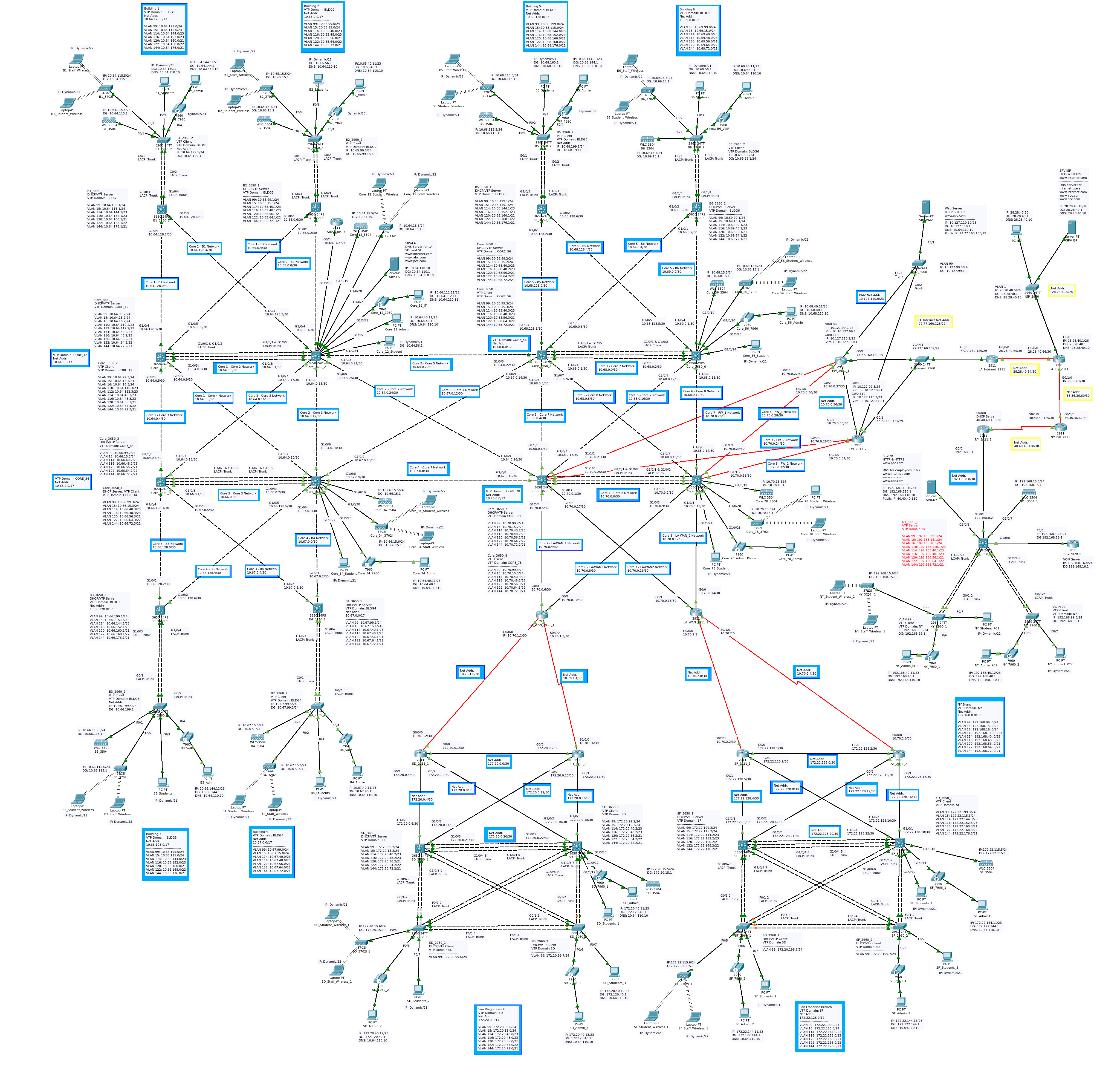
Figure 1a
Introduction
This topology was configured as the final project for the class CIS042 - CCNA: Routing, Switching, and Wireless Essentials at Pasadena City College. The class covered a subset of topics which are a part of the CCNA certification. On this page and in subsequent posts I’ll go through the various components of the network and show how everything comes together. All of the intermediary devices are Cisco devices. Where relevant I’ll include, or link to, IOS configurations. All of the IOS configuration commands are expected to be entered in global configuration mode. You’ll be able to download all of the configurations at the bottom of this page. I’ll go over the following topics as they relate to this network:
First an overview of the topology.
Overview
There is quite a bit going on here but the individual pieces are not too complicated. First we can take a look at one of the specification documents from my professor.
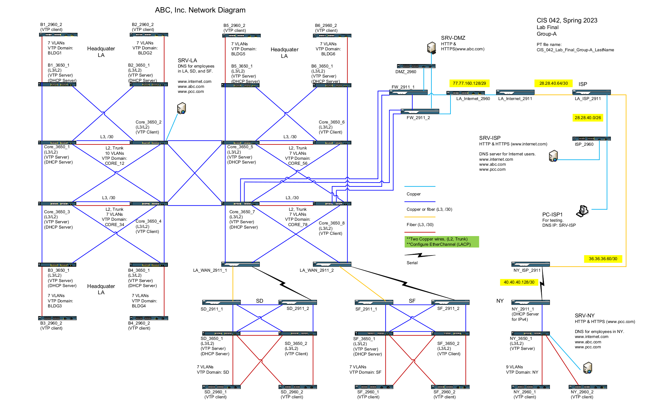 Figure 2a
This diagram provides valuable data about the network layout and device roles. Using this information, with some additional specifications/instructions, I created and configured the Packet Tracer topology pictured at the top of this page. Below, I have highlighted different regions of the network to help explain the layout. As this document progresses, I will explain the network components in greater detail.
All of the blue and yellow outlined labels in the topology diagrams contain information about the network addresses of a particular section of the network. All other labels are for device configurations/names and port IP addresses. All layer-3 ports are labeled with an IP address. In Figure 2b the different geographical sites are circled:
Figure 2b
- Los Angeles: Blue
- San Diego: Red
- San Francisco: Fuchsia
- New York: Yellow
- The Internet: Green
Los Angeles, San Diego, and San Francisco are all in the same private network using subnets from 10.0.0.0/8 and 172.16.0.0/12 address blocks. These two sites are composed of numerous physical subnets and VLANs, with routing provided by EIGRP. All of the private networks implement DHCP for select VLANS. New York is privately addressed using the 192.168.0.0/16 address block and all routing is static at this site. The “Internet” uses public IP addresses and, in this model, consists of a few routers, a server, and a client PC. NAT provides a bridge between the public and private networks. The private networks also feature VoIP phones. The VoIP phone system in NY is not connected to the one which covers LA, SD, and SF.
Los Angeles
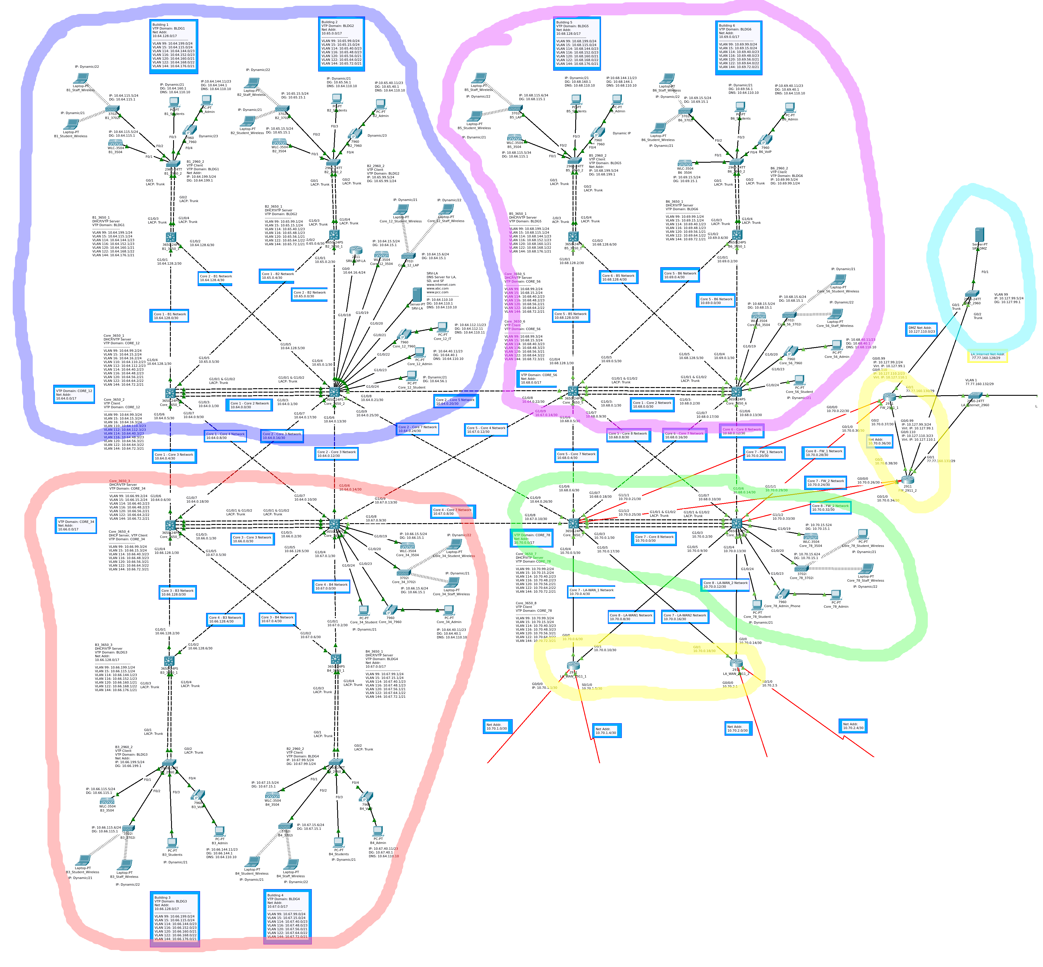 Figure 2c
Figure 2c is a closeup of the Los Angeles network. The logical diagram covers 6 buildings. The blue, yellow, and fuchsia regions are core VTP domains and their connected buildings. The core consists of eight layer-3 switches in an interVLAN failover configuration. Taking a closer look at the Core-1 / Core-2 subsection of the LA network, we can better understand the site as a whole. With some exceptions, the configuration of this site is mirrored in two more locations. Figure 2d is a closeup of the following VTP domains: CORE_12, BLDG1, and BLDG2.
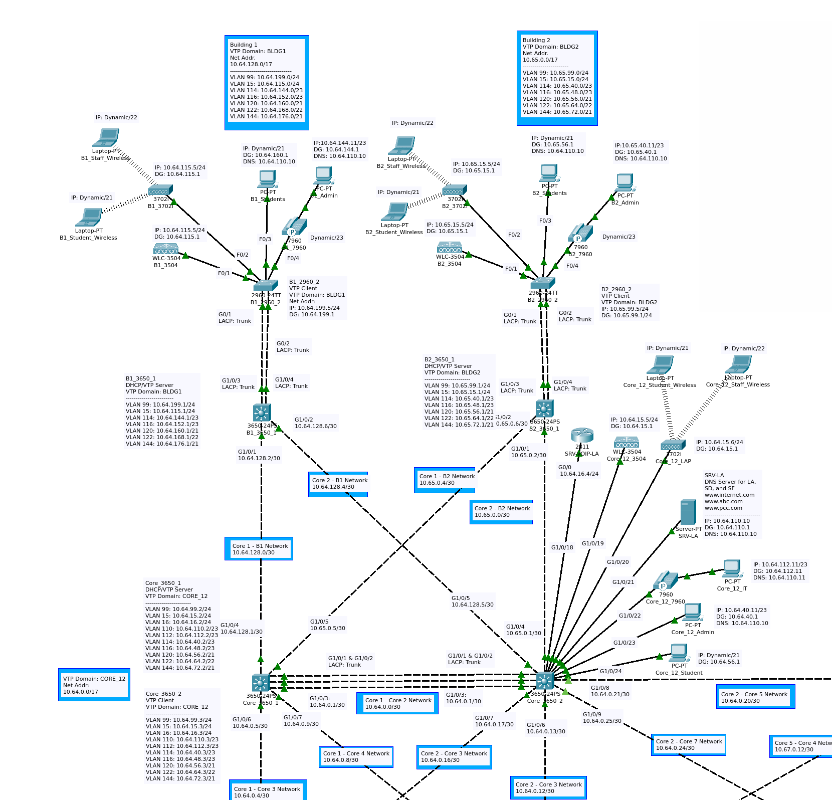 Figure 2d
Two devices, Core_3650_1 and Core_3650_2, form the core layer in this section of the network. They share a layer-3 link and an EtherChannel connection. Core_3650_2 has a number of end devices attached: a VoIP server, a DNS/Web Server, a WLC (Wireless LAN controller), a LAP (Lightweight Access Point), a VoIP phone, and several host PCs. Both of the core switches are connected to the distribution switches B1_3650_1 and B2_3650_1 via layer-3 links. Each distribution link is then connected via EtherChannel trunk to an access switch. Each layer-2 switch supports a WLC, LAP, and several host devices. The pairs Core_3650_3/Core_3650_4 and Core_3650_5/Core_3650_6 have the same basic layout as the first two cores, but they don’t have VoIP servers, there is not a IT-PC or an IT VLAN, and there is not a Server or server VLAN.
Core Edge Connections
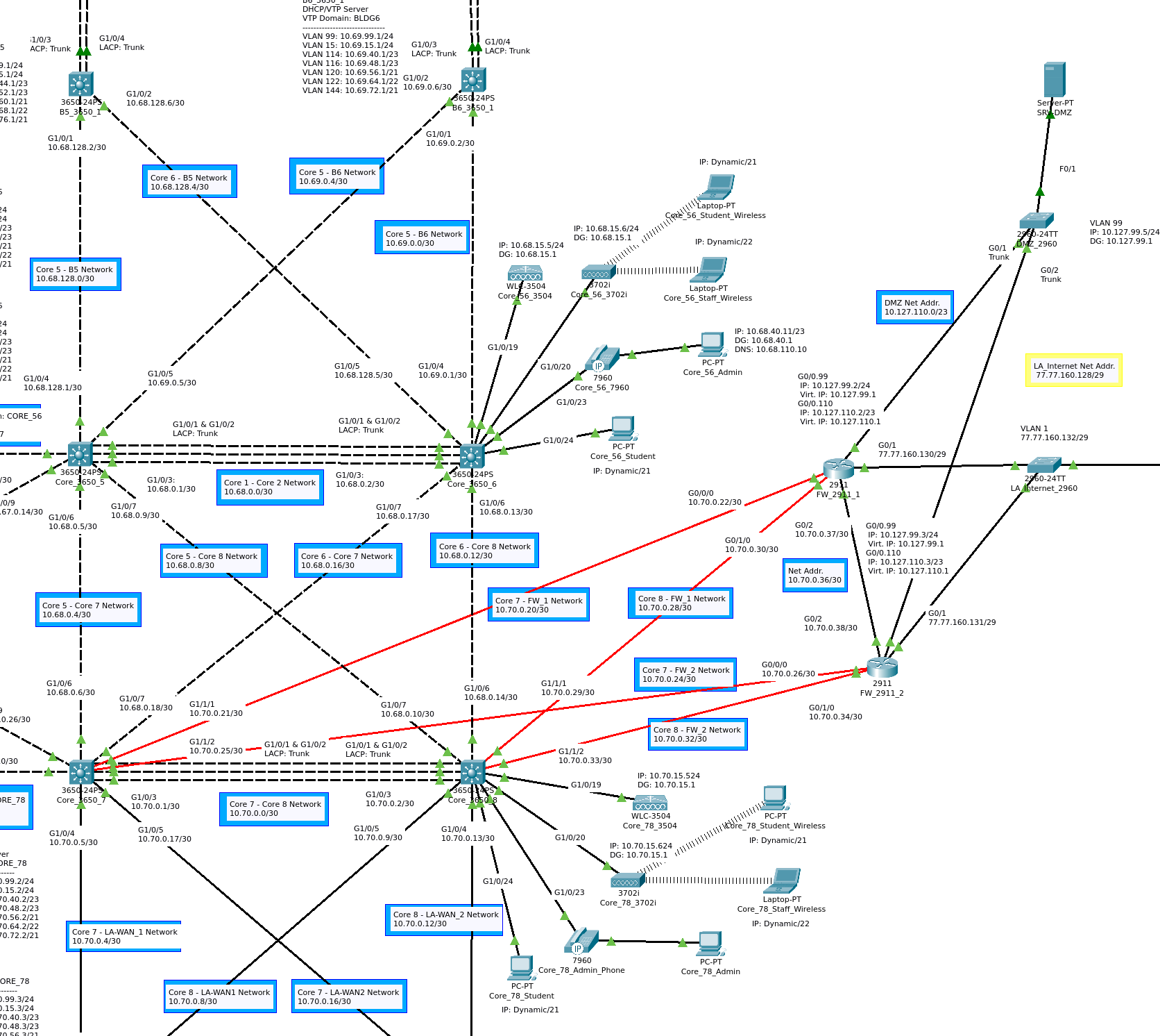 Figure 2e
In Figure 2e, Core_3650_7 and Core_3650_8 are circled in green. They serve as the connection to the edge routers, circled in yellow, which form the internet gateway. Two 2911 routers, circled in blue, are connected to this section of the core. They attach the core to the dedicated fiber and serial connections to the San Diego and San Francisco sites. These connections are all redundant and will be discussed in greater detail below. The network uses two routers, FW_2911_1 and FW_2911_2, which separate the private network from internet and DMZ.
San Diego and San Francisco
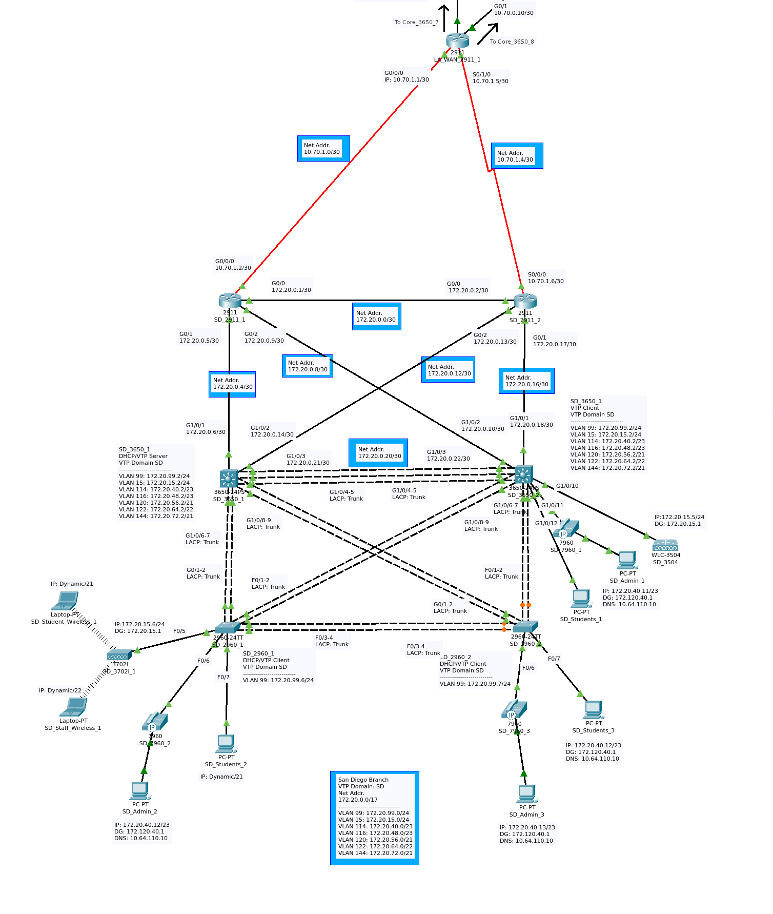 Figure 2f
The San Francisco and San Diego networks both use a topology which is part collapsed core and part mesh network. As they both use an identical topology, we can take a closer look at the San Diego network in Figure 2f to understand the two sites. The EtherChannel connections between the layer-2 and layer-3 switches combined with the connections to the 2911 routers, affords a high degree of redundancy. Similar to the previously discussed subsections, this site also features: a number of hosts, a WLC , a LAP, and VoIP phones. Each of these sites is connected to CORE_78 by two 2911 routers in a redundant configuration.
New York
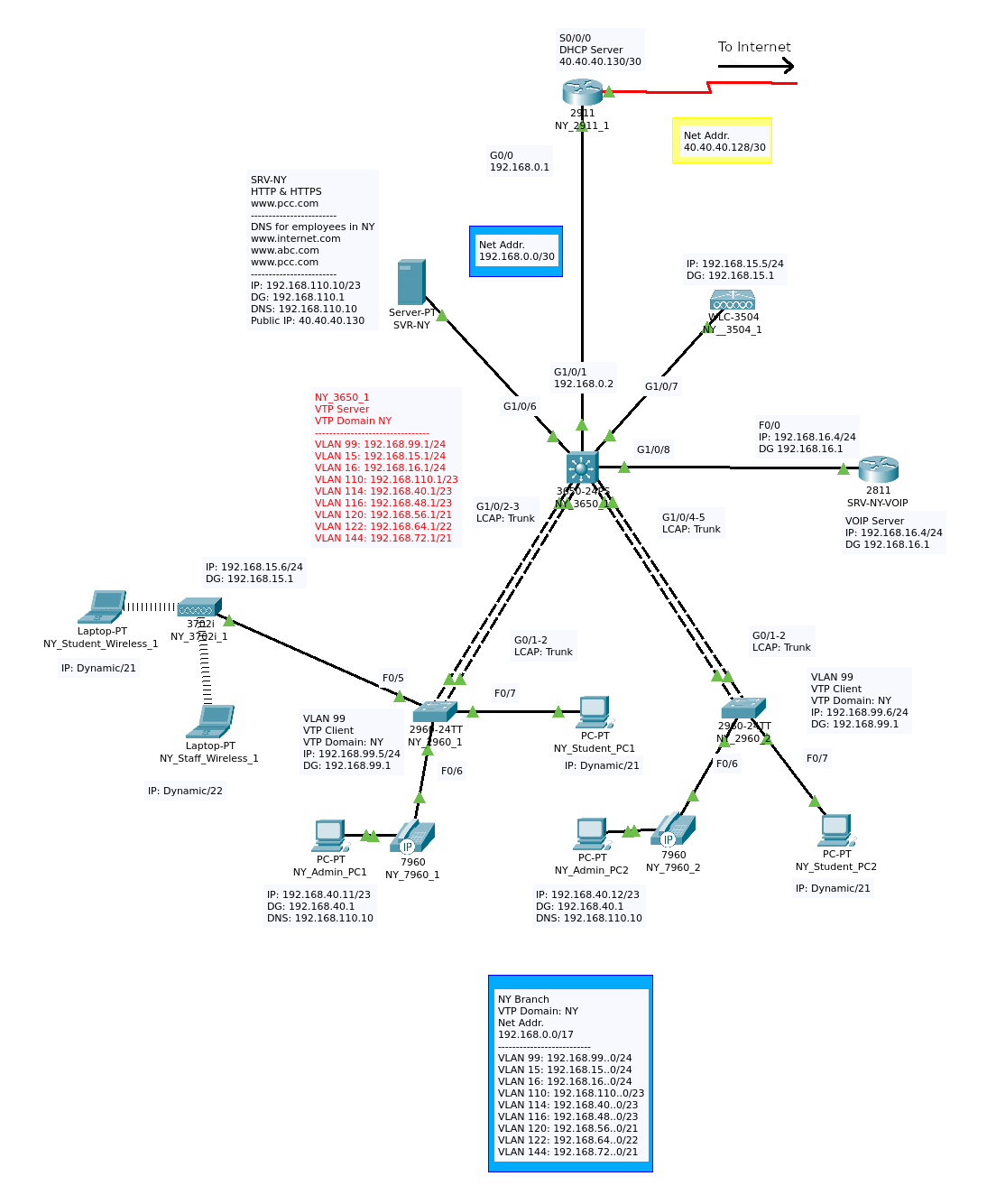
Figure 2g
This site uses a single core switch connected to two layer-2 access switches via EtherChannel. It has its own VoIP server/network and DNS/Web server. Like the other sites, it has a WLC, LAP, several hosts, and VoIP phones.
The Internet
This model internet is simply several routers creating layer-3 separation, and thus the need for routing. End devices in this area of the network are a server, and a computer. The server provides a public website for the private hosts to access and acts as a DNS server for the PC on the public net.
Design Constraints / The Problem
My professor provided the class with two documents to constrain the students in their network designs. The first is the logical topology pictured in Figure 3a below. It contains all of the intermediary devices, the media used to connect them and most of the servers. In addition, the role of each device is listed and some of the required functions. The next was a document providing specific information about subnetting, required functionality, and configuration constraints. I will include this information throughout the document as is needed.
Figure 3a
Subnets, VLANs, and InterVLAN Routing
As per the design constraints a number of VLANs were required. Blocks of IP addresses were provided such that subnets could be carved out for all of the VLANs.
VLAN Constraints
- LA office, use 10.64.0.0/10.
- Each VTP domain, use /17
- SD office, use 172.20.0.0/17.
- SF office, use 172.22.128.0/17.
- NY office, use 192.168.0.0/17.
The VLAN numbers, names, and subnet masks were also provided. In addition, VTP domain names were given.
Core_3650_1 and Core_3650_2:
- VLAN 99: Management and Native, /24
- VLAN 15: WLC and AP, /24
- VLAN 16: VoIP Server, /24
- VLAN 110: Servers, /23
- VLAN 112: IT, /23
- VLAN 114: Admins, /23
- VLAN 116: VoIP Phones, /23
- VLAN 120: Students, /21
- VLAN 122: Wireless (SSID: staff-xx, xx is the VTP domain name.), /22
- VLAN 144: Wireless (SSID: students-xx, xx is the VTP domain name.), /21
NY:
- VLAN 1: Management and Native, /24
- VLAN 15: WLC and AP, /24
- VLAN 16: VoIP Server, /24
- VLAN 110: Servers, /23
- VLAN 114: Admins, /23
- VLAN 116: VoIP Phones, /23
- VLAN 120: Students, /21
- VLAN 122: Wireless (SSID: staff-xx, xx is the VTP domain name.), /22
- VLAN 144: Wireless (SSID: students-xx, xx is the VTP domain name.), /21
Others:
- VLAN 99: Management and Native, /24
- VLAN 15: WLC and AP, /24
- VLAN 114: Admins, /23
- VLAN 116: VoIP Phones, /23
- VLAN 120: Students, /21
- VLAN 122: Wireless (SSID: staff-xx, xx is the VTP domain name.), /22
- VLAN 144: Wireless (SSID: students-xx, xx is the VTP domain name), /21
DMZ:
- VLAN 99: Management and Native, /24
- VLAN 110: Servers, /23
Subnetting
Having read ahead in the spec, I knew the ability to summarize routes would be useful. EIGRP and NAT ACLs are easier to configure if the subnets are well thought out. So I devised a subnetting strategy which segregated the logical sections of the network, while remaining within spec. For the core, distribution, and access subsections, I created a /15 supernet which was then subnetted into 3 /17 VTP domains. This made it possible to refer to one of these core subsections with a single network address. These are my notes for the VTP domains CORE_12, BLDG1, BLDG2 and their VLANs:
VTP Domain: CORE_12 — Subnet: 10.64.0.0/17 — Supernet: 10.64.0.0/15
| VLAN | VLAN Subnet | Name |
|---|---|---|
| VLAN 99 | 10.64.99.0/24 | : Management and Native |
| VLAN 15 | 10.64.15.0/24 | : WLC and AP |
| VLAN 16 | 10.64.16.0/24 | : VoIP Server |
| VLAN 110 | 10.64.110.0/23 | : Servers |
| VLAN 112 | 10.64.112.0/23 | : IT |
| VLAN 114 | 10.64.40.0/23 | : Admins |
| VLAN 116 | 10.64.48.0/23 | : VoIP Phones |
| VLAN 120 | 10.64.56.0/21 | : Students |
| VLAN 122 | 10.64.64.0/22 | : Wireless (SSID: staff-CORE_12) |
| VLAN 144 | 10.64.72.0/21 | : Wireless (SSID: students-CORE_12) |
| Point to Point IPs | 10.64.0.0-252/30 | N/A |
VTP Domain: BLDG1 — Subnet: 10.64.128.0/17 — Supernet: 10.64.0.0/15
| VLAN | VLAN subnet | Name |
|---|---|---|
| VLAN 99 | 10.64.199.0/24 | : Management and Native, /24 |
| VLAN 15 | 10.64.115.0/24 | : WLC and AP, /24 |
| VLAN 114 | 10.64.144.0/23 | : Admins, /23 |
| VLAN 116 | 10.64.152.0/23 | : VoIP Phones, /23 |
| VLAN 120 | 10.64.160.0/21 | : Students, /21 |
| VLAN 122 | 10.64.168.0/22 | : Wireless (SSID: staff-BLDG1), /22 |
| VLAN 144 | 10.64.176.0/21 | : Wireless (SSID: students-BLDG1), /21 |
| Point to Point IPs | 10.64.128.0-252/30 | N/A |
VTP Domain: BLDG2 — Subnet: 10.65.0.0/17 — Supernet: 10.64.0.0/15
| VLAN | VLAN subnet | Name |
|---|---|---|
| VLAN 99 | 10.65.99.0/24 | : Management and Native, /24 |
| VLAN 15 | 10.65.15.0/24 | : WLC and AP, /24 |
| VLAN 114 | 10.65.40.0/23 | : Admins, /23 |
| VLAN 116 | 10.65.48.0/23 | : VoIP Phones, /23 |
| VLAN 120 | 10.65.56.0/21 | : Students, /21 |
| VLAN 122 | 10.65.64.0/22 | : Wireless (SSID: staff-BLDG2), /22 |
| VLAN 144 | 10.65.72.0/21 | : Wireless (SSID: students-BLDG2), /21 |
| Point to Point IPs | 10.65.0.0-252/30 | N/A |
Using these network address sets, I was able to create subnets for the remaining private networks by altering the first 2 octets. This simplified the build out process, and made troubleshooting much easier. In the downloads section, you can find the full excel spreadsheet which contains the rest of the network addresses.
Host Addresses
I chose a convention for the last octet of host IP addresses which was based on device type, and the knowledge that HSRP would later be implemented. Those are as follows:
| Device Type | Last Octet Value |
|---|---|
| HSRP Virtual IP | 1 |
| HSRP Primary | 2 |
| HSRP Standby | 3 |
| Distribution Layer-3 Switch VLI | 1 |
| Layer-2 Switch VLI | 5,6,7 |
| Web/DNS Server | 10 |
| Static PC hosts | 11 |
| WLC | 5 |
| LAP | 6 |
Armed with these design decisions and constraints, I created the logical packet tracer topology. This process locked in the IP addressing for all devices, and paved the way for configuration which starts with setting up interVLAN routing.
InterVLAN Routing
InterVLAN routing is achieved in two ways: native layer-3 switch routing or router-on-a-stick. To see how native interVLAN routing works, we can take a look at how B1_3650_1 and B1_2960_2 are configured.
Native InterVLAN Routing
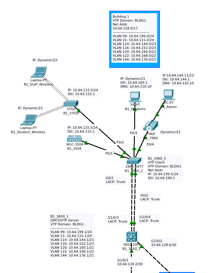 Figure 4a
The first step in setting interVLAN routing is configuring the SVIs (Switched Virtual Interfaces). This is achieved by:
- Enabling IPv4 interVLAN routing
- Naming the interface (optional)
- Setting the IP address of the interface
- Repeat 1-3 until all interfaces are configured
Here’s what that looks like in the case of B1_3650_1:
ip routing
!
!
vlan 99
 name Management/Native
interface vlan 99
 ip address 10.64.199.1 255.255.255.0
!
vlan 15
 name WLC/AP
interface vlan 15
 ip address  10.64.115.1 255.255.255.0
!
VLAN 114
 name Admins
interface vlan 114
 ip address 10.64.144.1 255.255.254.0
!
VLAN 116
 name VoIP-Phones
 interface VLAN 116
 ip address 10.64.152.1 255.255.254.0
!
VLAN 120
 name Students
interface VLAN 120
 ip address 10.64.160.1 255.255.248.0
!
VLAN 122
  name Staff-Wireless
interface vlan 122
 ip address 10.64.168.1 255.255.252.0
!
VLAN 144
 name Student-Wireless
 interface vlan 144
 ip address 10.64.176.1 255.255.248.0
B1_3650_1 has a layer-2 switch connected to it via trunk. B1_2960_2 separates its connected devices into VLANs, and the routing is provided by B1_3650_1. The trunk connection is over EtherChannel, so we have to configure the port-channel on both devices. I’ll describe the EtherChannel configurations in another section. In this network, the native VLAN is 99 on all devices. The commands to complete this task are as follows:
interface range GigabitEthernet 1/0/3-4
 channel-group 1 mode active
!
interface port-channel 1
 switchport mode trunk
 switchport trunk native vlan 99
Setting up the VLANs on B2_2960_2 requires configuration of a VLAN interface, trunk configuration, and access port configuration.
There is only one VLAN interface required on B1_2650_2, it is for native and management traffic. The configuration can be completed with the following commands:
interface vlan 99
 ip address 10.64.199.5 255.255.255.0
The trunk configuration for the port-channel on B1_2960_2 is as follows:
interface range GigabitEthernet 0/1-2
 channel-group 1 mode active
!
interface port-channel 1
 switchport mode trunk
 switchport trunk native vlan 99
The final step is configuring the access ports for devices which access the network through B1_2960_2.
FastEthernet ports 0/1 and 0/2 provide access to devices on on the WCL/AP VLAN which requires a trunked connection with the native VLAN set to 15:
interface range FastEthernet 0/1-2
 switchport mode trunk
 switchport trunk native vlan 15
FastEthernet0/3 is connected to the student wired network:
interface FastEthernet 0/3
 switchport access vlan 120
FastEthernet0/4 connects a phone to the VoIP VLAN and a PC to the Admin VLAN:
interface FastEthernet 0/4
 switchport access vlan 114
 switchport voice vlan 116
Router-on-a-Stick
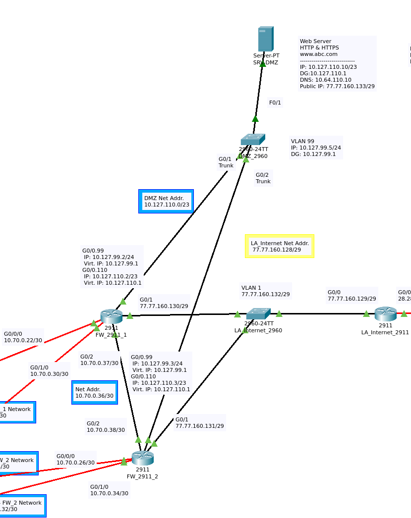 Figure 4b
In the DMZ there is a layer-2 switch which has two VLANs, one for native traffic and the other for server traffic. The default gateway for the VLAN interface on DMZ_2960 is the virtual IP address of the HSRP configured routers FW_2911_1 and FW_2911_2. Each router actually has 2 sub interfaces, one for the native VLAN and one for the server net. There is a section on HSRP below where I describe this failover setup in more detail.
VTP (Virtual Trunking Protocol)
This protocol simplifies VLAN management by allowing a switch to share its VLAN configurations with other switches. The switch which shares its configuration is the VTP server, and switches which receive configuration are VTP clients. We can look at the configuration of B1_3650_1 and B1_2960_2 to see how VTP is set up.
Figure 5a
To configure B1_3650_1 as a VTP server, we simply set it’s VTP domain and set the VTP mode to server:
vtp mode Server
vtp domain BLDG1
Configuring VTP clients is just as simple, but there is potential for problems. The default operation mode for VTP is server. If the domain is set before the VTP mode is changed to client, it is possible for the device to transmit the wrong configurations to VTP clients on the network. This can cause serious problems. Before setting the VTP domain of the client, the mode should be set to the client.
vtp mode client
vtp domain BLDG1
Once this configuration is complete, the VLANs names on the client switch will reflect the current settings on the server. Any changes made to the VTP settings on the server are propagated to the client.
EtherChannel
This technology allows a network technician to aggregate multiple layer-2 connections between switching devices. The benefit is twofold, both the bandwidth and redundancy of the connection are increased. In the event of port or media failure, as long as one physical connection remains, the layer-2 link can remain functional. All of the channel groups in this topology are formed with LACP (Link Aggregation Control Protocol), and the mode of both sides is set to active. I mentioned EtherChannel in the interVLAN routing section, let’s take a look at how it is configured using B1_3650_1 and B1_2960_2 as examples:
Figure 6a
The EtherChannel protocol and negotiation type are both explicitly set for these two devices. Interface configuration mode is entered on ports GigabitEthernet 1/0/3 and 1/0/4 on B1_3650_1 with the ‘interface range’ command. Then the channel-group and mode are set:
interface range GigabitEthernet 1/0/3-4
 channel-group 1 mode active
On B1_2960_2 the configuration is the same but the port numbers differ:
interface range GigabitEthernet 0/1-2
 channel-group 1 mode active
DHCP
Figure 8a
There are four VLANs on the network which use DHCP: VoIP-Phones, Students, Student-Wireless, and Staff-Wireless. DHCP in all cases, for this network, is served by a Cisco router or layer-3 switch.
Local DHCP
In the case of B1_3650_1 the following local DHCP configuration was used:
!
! DHCP Config
!
! Student Vlan 120
ip dhcp excluded-address 10.64.160.1 10.64.160.10
ip dhcp pool VLAN120
 network 10.64.160.0 255.255.248.0
 default-router 10.64.160.1
 dns-server 10.64.110.10
 domain-name abc.com
!
! VoIP DHCP
ip dhcp excluded-address 10.64.152.1 10.64.152.10
ip dhcp pool VOIP116
 network 10.64.152.0 255.255.254.0
 default-router 10.64.152.1
 dns-server 10.64.110.10
 option 150 ip 10.64.16.4
 domain-name abc.com
!
!Staff Wireless
ip dhcp excluded-address 10.64.168.1 10.64.168.10
ip dhcp pool STAFF-WIRLESS-122
 network 10.64.168.0 255.255.252.0
 default-router 10.64.168.1
 dns-server 10.64.110.10
 domain-name abc.com
 !
! Student Wireless
ip dhcp excluded-address 10.64.176.1 10.64.176.10
ip dhcp pool STUDENT-WIRELESS-144
 network 10.64.176.0 255.255.248.0
 default-router 10.64.176.1
 dns-server 10.64.110.10
 domain-name abc.com
 !
service dhcp
A DHCP pool is configured for each VLAN. For each DHCP pool several parameters are set: excluded addresses, network address, default router/gateway, dns server, and a domain name. The VoIP DHCP configuration is special and has an extra command:
option 150 ip 10.64.16.4
This command lets the VoIP phones which receive a configuration know the IP address of the VoIP server.
Remote DHCP
The network in New York make use of a remote DHCP server and DHCP relay:
Figure 7b
NY_2911 is used as the DHCP server for this site; the configuration is quite similar to the configuration on B1_3650_1:
ip dhcp excluded-address 192.168.56.1 192.168.56.10
ip dhcp pool VLAN120
 network 192.168.56.0 255.255.248.0
 default-router 192.168.56.1
 dns-server 192.168.110.10
 domain-name pcc.com
!
! VoIP DHCP
ip dhcp excluded-address 192.168.48.1 192.168.48.10
ip dhcp pool VOIP116
 network 192.168.48.0 255.255.254.0
 default-router 192.168.48.1
 dns-server 192.168.110.10
 option 150 ip 192.168.16.4
 domain-name pcc.com
!
!Staff Wireless
ip dhcp excluded-address 192.168.64.1 192.168.64.10
ip dhcp pool STAFF-WIRLESS-122
 network 192.168.64.0 255.255.252.0
 default-router 192.168.64.1
 dns-server 192.168.110.10
 domain-name pcc.com
 !
! Student Wireless
ip dhcp excluded-address 192.168.72.1 192.168.72.10
ip dhcp pool STUDENT-WIRELESS-144
 network 192.168.72.0 255.255.248.0
 default-router 192.168.72.1
 dns-server 192.168.110.10
 domain-name pcc.com
There is layer-3 separation between the DHCP clients and the server, so NY_3650_1 needs configuration as a DHCP relay. Each of the SVIs on NY_3650_1 receives a helper-address configuration. This information allows the SVI to transact DHCP traffic between clients and the remote server. The configuration for the VLANs on which DHCP is configured is shown below:
VLAN 116
 name VoIP-Phones
 interface VLAN 116
 ip address 192.168.48.1  255.255.254.0
 ip helper-address 192.168.0.1
 !
VLAN 120
 name Students
interface VLAN 120
 ip address 192.168.56.1  255.255.248.0
 ip helper-address 192.168.0.1
 !
VLAN 122
  name Staff-Wireless
 interface vlan 122
 ip address 192.168.64.1  255.255.252.0
 ip helper-address 192.168.0.1
 !
VLAN 144
 name Student-Wireless
 interface vlan 144
 ip address 192.168.72.1  255.255.248.0
 ip helper-address 192.168.0.1
HSRP (Hot Standby Redundancy Protocol)
HSRP is a proprietary Cisco First Hop Redundancy Protocol. The goal of protocol is to provide redundancy for gateway devices. This is achieved by grouping gateways such that there is primary and one or more standby gateways. If the primary gateway becomes inaccessible, a standby gateway will take over. The gateways use multicast hello messages to each other to share their priorities (the preferred gateway) and current status (standby or active).
InterVLAN Routing and HSRP
The core switches in this network are grouped in pairs. Each SVI on a core is grouped with the corresponding SVI on the paired core. The SVIs on the odd cores are active and while the SVIs on the even cores are standby. In this setup the active gateways are set to preempt the standbys. Each pair is connected by an EtherChannel link and a Layer-3 link. It is over the EtherChannel link that failover communication occurs. Below are the VLAN interface configurations for Core_3650_1:
vlan 99
 name Management/Native
interface vlan 99
 ip address 10.64.99.2 255.255.255.0
 standby 99 ip 10.64.99.1
 standby 99 priority 200
 standby 99 preempt
!
vlan 15
 name WLC/AP
interface vlan 15
 ip address  10.64.15.2 255.255.255.0
 standby 15 ip 10.64.15.1
 standby 15 priority 200
 standby 15 preempt
!
VLAN 16
 name VoIP-Server
interface vlan 16
 ip address 10.64.16.2 255.255.255.0
 standby 16 ip 10.64.16.1
 standby 16 priority 200
 standby 16 preempt
 !
VLAN 110
 name Servers
interface vlan 110
 ip address 10.64.110.2 255.255.254.0
 standby 110 ip 10.64.110.1
 standby 110 priority 200
 standby 110 preempt
 !
VLAN 112
 name IT
interface vlan 112
 ip address 10.64.112.2 255.255.254.0
 standby 112 ip 10.64.112.1
 standby 112 priority 200
 standby 112 preempt
 !
VLAN 114
 name Admins
interface vlan 114
 ip address 10.64.40.2 255.255.254.0
 standby 114 ip 10.64.40.1
 standby 114 priority 200
 standby 114 preempt
 !
VLAN 116
 name VoIP-Phones
 interface VLAN 116
 ip address 10.64.48.2 255.255.254.0
 standby 116 ip 10.64.48.1
 standby 116 priority 200
 standby 116 preempt
 !
VLAN 120
 name Students
interface VLAN 120
 ip address 10.64.56.2 255.255.248.0
 standby 120 ip 10.64.56.1
 standby 120 priority 200
 standby 120 preempt
 !
VLAN 122
  name Staff-Wireless
 interface vlan 122
 ip address 10.64.64.2 255.255.252.0
 standby 122 ip 10.64.64.1
 standby 122 priority 200
 standby 122 preempt
 !
VLAN 144
 name Student-Wireless
 interface vlan 144
 ip address 10.64.72.2 255.255.248.0
 standby 144 ip 10.64.72.1
 standby 144 priority 200
 standby 144 preempt
Each of the VLAN interfaces has a physical IP, but also requires a virtual/standby IP. The HSRP priority is set is set 200 and preempt is set. These two commands ensure that these VLAN interfaces will be the active interfaces if they are up. Priority 200 is higher than the default, which the standby VLAN interfaces are set to, causing these interfaces to win the HSRP election. The preempt setting forces a new election when any of these interfaces goes from down to up. The commands for the Core3650_2 are below:
 interface vlan 99
 ip address 10.64.99.3 255.255.255.0
 standby 99 ip 10.64.99.1
!
interface vlan 15
 ip address  10.64.15.3 255.255.255.0
 standby 15 ip 10.64.15.1
!
interface vlan 16
 ip address 10.64.16.3 255.255.255.0
 standby 16 ip 10.64.16.1
 !
interface vlan 110
 ip address 10.64.110.3 255.255.254.0
 standby 110 ip 10.64.110.1
 !
interface vlan 112
 ip address 10.64.112.3 255.255.254.0
 standby 112 ip 10.64.112.1
 !
interface vlan 114
 ip address 10.64.40.3 255.255.254.0
 standby 114 ip 10.64.40.1
 !
 interface VLAN 116
 ip address 10.64.48.3 255.255.254.0
 standby 116 ip 10.64.48.1
 !
interface VLAN 120
 ip address 10.64.56.3 255.255.248.0
 standby 120 ip 10.64.56.1
 !
 interface vlan 122
 ip address 10.64.64.3 255.255.252.0
 standby 122 ip 10.64.64.1
 !
 interface vlan 144
 ip address 10.64.72.3 255.255.248.0
 standby 144 ip 10.64.72.1
HSRP on the Internet Gateways and Failover
As mentioned earlier, two routers provide a gateway to the internet for the private network for sites Los Angeles, San Francisco and San Diego. These two routers perform some important functions:
- Dynamic NAT
- Static NAT for the server SRV-DMZ
- InterVLAN routing for DMZ_2960
- Gateways between the private a public network
They are set up in an HSRP group, so internet connectivity for the private networks will remain if one of these routers is taken offline. Take a look at Figure 8a to see how this section of the network is layed out.
Figure 8a
FW_2911_1 is the active router in a standby group with FW_2911_2. Each router has five connections:
- To Core_3650_7
- To Core_3650_8
- To DMZ_2960
- To the other gateway router.
- To LA_internet_2960
First let’s look at the Core connections. Routing between the cores and the routers is governed by EIGRP; failover for these connections is achieved by dynamic routing.
The DMZ connections on each router make use of HSRP. Interface GigabitEthernet 0/0 on each router is configured with 2 sub-interfaces. These sub-interfaces use dot1q encapsulation to perform interVLAN routing for the VLANs on DMZ_2960. The configuration for these interfaces is shown below:
FW_2911_1
interface GigabitEthernet 0/0.99
 standby 99 ip 10.127.99.1
 standby 99 priority 200
 standby 99 preempt
!
interface GigabitEthernet 0/0.110
 standby 110 ip 10.127.110.1
 standby 110 priority 200
 standby 110 preempt
FW_2911_2
interface GigabitEthernet 0/0.99
 standby 99 ip 10.127.99.1
!
interface GigabitEthernet 0/0.110
 standby 110 ip 10.127.110.1
!
These configurations set FW_2911_1 as the active router.
A Brief Tangent to Complete the Failover Configuration
Interface GigabitEthernet 0/2 connects FW_2911_1 to FW_2911_2, this connection exists to fix a quirk of this router configuration. It exists so FW_2911_2 can forward packets it receives which need to reach the default gateway to FW_2911_1. This is a achieved by setting two static routes on FW_2911_2 using these commands:
ip route 0.0.0.0 0.0.0.0 77.77.160.129 5
!
ip route 0.0.0.0 0.0.0.0 GigabitEthernet 0/2
The first command routes traffic for the default route to Internet_2960. With a metric 5, this first route will be superseded by the route in the following command because it has a lower metric. During normal operation the static route to GigabitEthernet 0/2 is up, and so packets without a destination in the routing table are forwarded to FW_2911_1.
Why is all this necessary? EIGRP attempts to optimize traffic by alternating paths to the internet when packets exit Core_3650_7 or Core_3650_8 toward the internet. If the static route from FW_2911_1 to FW_2911_2 is not configured, problems arise for the TCP 3-way handshake. For a handshake to work over NAT, all of the packets exiting the private network need NAT performed on the same router. If both gateway routers have a route of last resort in their routing table, the SYN and ACK portions of the handshake may not exit the network at the same point. Let’s look at an example for a PC on private network establishing a connection to a server:
PC Core_78_Admin wants to open TCP connection to server ISP-SVR to download a webpage. First, the PC sends TCP SYN to the server. The packet exits the private network via FW_2911_1 using NAT and a public IP. Next, the server responds with SYN/ACK. The packet reaches the PC, which then sends back an ACK to complete the handshake. This packet exits FW_2911_2, this breaks the handshake.
HSRP, EIGRP, a floating static route come together to provide redundancy for default gateway of the private network, access to the DMZ, and interVLAN routing for DMZ_2960.
In order for this failover configuration to work correctly, a standby router must perform all of the same functions as the active router. NAT is one of the mirrored functions, in the next section we’ll see how that is configured.
NAT (Network Address Translation)
This network uses NAT to exchange packets between the private and public networks. Two types of NAT are present, servers utilize a static public IP and other hosts are assigned a dynamic public IP. The Los Angeles, San Diego, San Francisco networks access the internet through FW_2911_1 and FW_2911_2. Let’s take a look at that configuration on FW_2911_1.
PAT
To configure PAT we need to set make the following configurations:
- Define the pool of public addresses which are available for assignment.
- Create an ACL to define which private IP address ranges should be translated.
- Declare the ports of the router as either inside or outside.
- Bind the previous elements together and activate dynamic NAT.
NAT POOL
We first need to figure out which IP addresses are available for NAT. There are four interfaces in this section of the network which need an IP address from the network 77.77.160.128/29: FW_2911_1, FW_2911_2, LA_Internet_2960, and LA_Internet_2911. That leaves 2 addresses available for NAT. 77.77.160.134/29 was selected as the ip address for the PAT configuration. The NAT pool can be configured with this command
ip nat pool NAT_POOL 77.77.160.134 77.77.160.134 netmask 255.255.255.248
NAT ACL
The router needs to know which IP addresses should be translated. This information is provided in the form of an ACL. Thanks to the organization of this network, only 2 rules are required for this ACL:
ip access-list extended NAT_ACL
 permit ip 10.64.0.0 0.63.255.255 any
 permit ip 172.20.0.0 0.3.255.255 any
I chose a named ACL here to make the running configuration easier to understand. The first rule permits rule devices from the Los Angeles site, and the second permits devices from San Diego and San Francisco.
Inside and Outside Interfaces
Each interface on the router must be configured as inside or outside, this configuration governs whether or not translation will occur. Here are those commands:
!
interface GigabitEthernet 0/0/0
 ip nat inside
!
interface GigabitEthernet 0/1/0
 ip nat inside
!
interface GigabitEthernet 0/2/0
 ip nat inside
!
interface GigabitEthernet 0/0.99
 ip nat inside
!
interface GigabitEthernet 0/0.110
 ip nat inside
!
interface GigabitEthernet 0/1
 ip nat outside
!
Enable PAT
The following command will bind the previous NAT configurations and start the dynamic NAT process:
ip nat inside source list NAT_ACL pool NAT_POOL overload
Static NAT
The DMZ server SRV_DMZ needs a static public IP address so devices can reliably reach it from the outside. This is setup with one command:
ip nat inside source static 10.127.110.10 77.77.160.133
The NAT configuration for the New York site is quite similar, check the configuration files in the downloads section if you want to see how that is set up.
VoIP
The Voice Over IP systems in the Los Angeles and New York networks supported by 2811 routers acting as servers, one in each network. We can take a look at the LA configuration to get an idea of how this works. The system is built on 3 things: the VoIP server, DHCP, and the phones. When a phone is connected to an access port it receives a configuration from the DHCP server on the VoIP VLAN. That message contains the address of the VoIP server. The phone connects to the server, is registered, and receives a phone number.
We’ve already seen the DHCP server configuration where option 150 is used to define the VoIP server IP, so let’s take a look at the VoIP server configuration. The following commands will start the server:
telephony-service
 max-ephones 40
 max-dn 50
 ip source-address 10.64.16.4 port 2000
 auto assign 31 to 50
Then we can set up a collection of ephone entries on the server so it can automatically register and assign a number to each phone. This is done with the following command:
ephone-dn 31
 number 1031
One entry is made per phone to be connected using the auto assign block. The zip file in the downloads section contains a python script to create phone entries.
WLCs and LAPs
Each VTP domain in the topology features a Wireless Lan Controller and a Lightweight Access Point. I can’t include the WLC CLI command line instructions as Packet Tracer only supports GUI configuration.
Conclusions
Configuring this network covered a lot of topics and I didn’t even include details about all of the features of this network. There is definitely room for improvement in this configuration. There are some features which could improve this network:
- Console and exec mode password protection
- port security
- A GRE/IPsec tunnel between LA and NY to interconnect the phone systems
- ASA gateways
I hope to post some configurations with security in mind soon!
Downloads
A zip archive with all of the configuration files.